RF Frequency Downconversion System
An analog RF receiver built from simulation to PCB: filtering, voltage protection, and downconversion to a 100 kHz output.
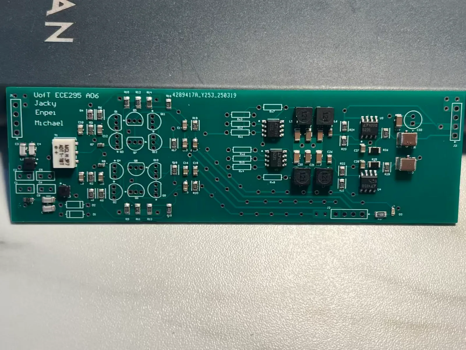
The result
A working RF receiver front end with 18 dB measured chain gain. Mixing a 10 MHz input with a 9.9 MHz local oscillator produced an output near 100 kHz.
| Parameter | Design or measured value |
|---|---|
| RF passband | 8–16 MHz |
| Limiter threshold | ±0.7 V |
| Downconverted output | ≈100 kHz |
| Measured chain gain | 18 dB |
| I/Q phase target | 90° ±12.5° |
Circuit design
The signal passes through an LC bandpass filter, opposing 1N4148 limiter diodes, a Gilbert-cell mixer, and a low-pass filter. A center-tapped transformer supplies balanced local-oscillator signals for the I/Q paths.
Our initial discrete mixer had 33.75 dB conversion loss. We redesigned it around an HFA3101 transistor array, then verified the circuit in LTspice and on a breadboard. The passive LC filter saved board area, at the cost of inductor loss.
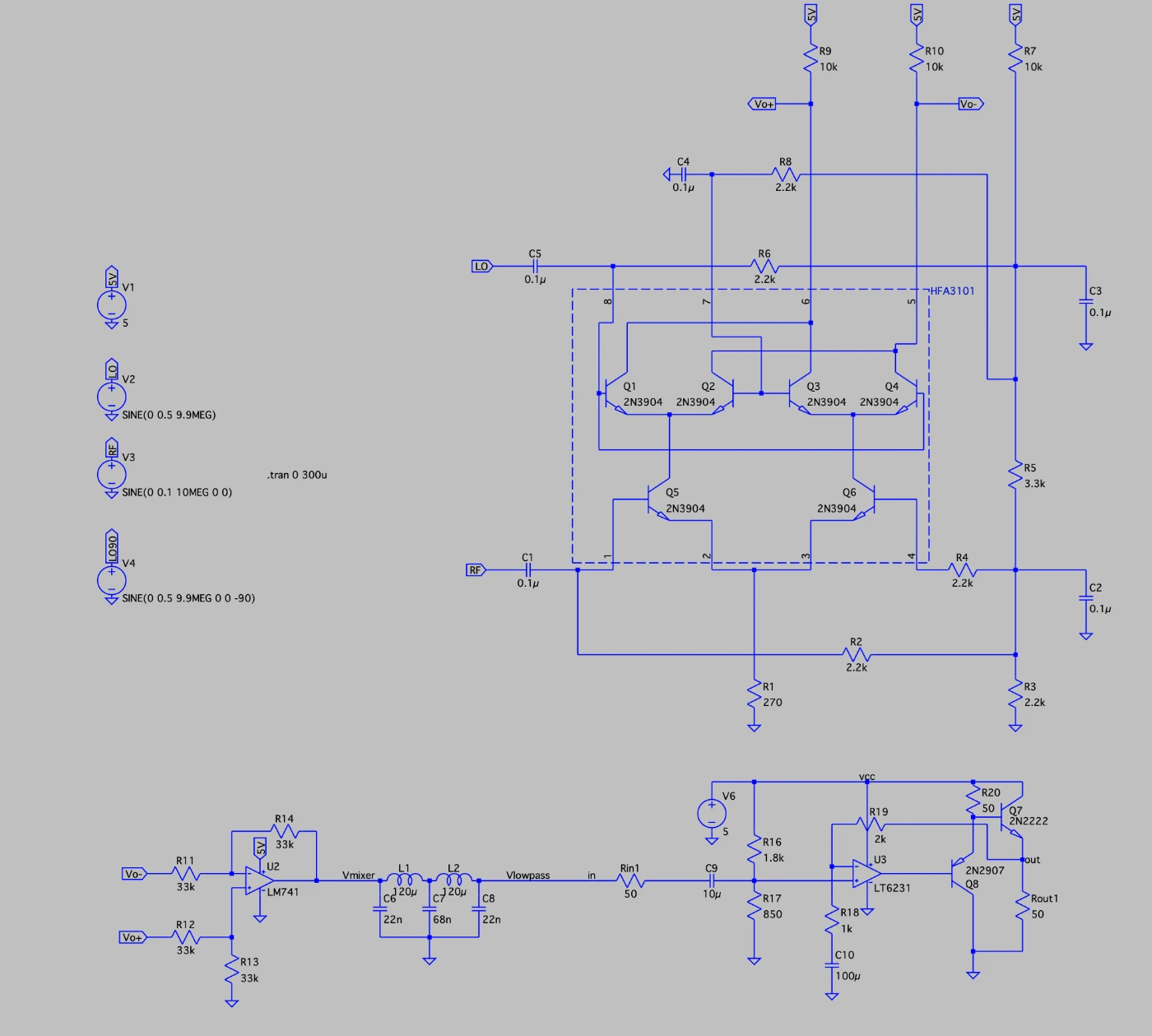
LTspice model of the revised mixer and output filter.
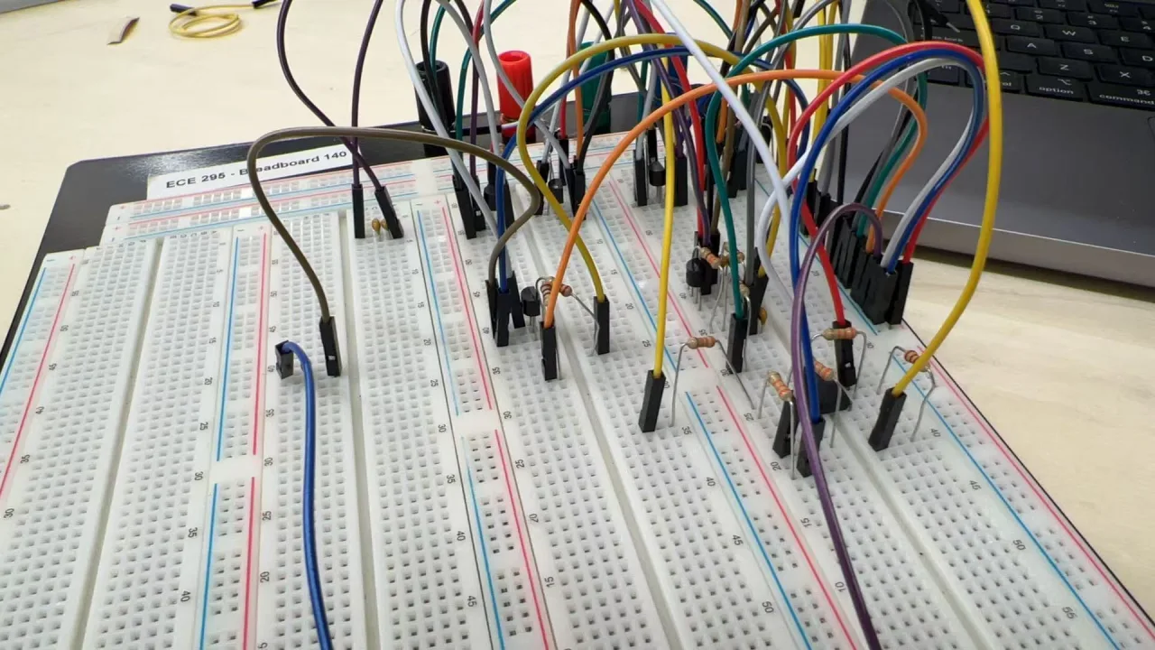
Breadboard validation before PCB layout.
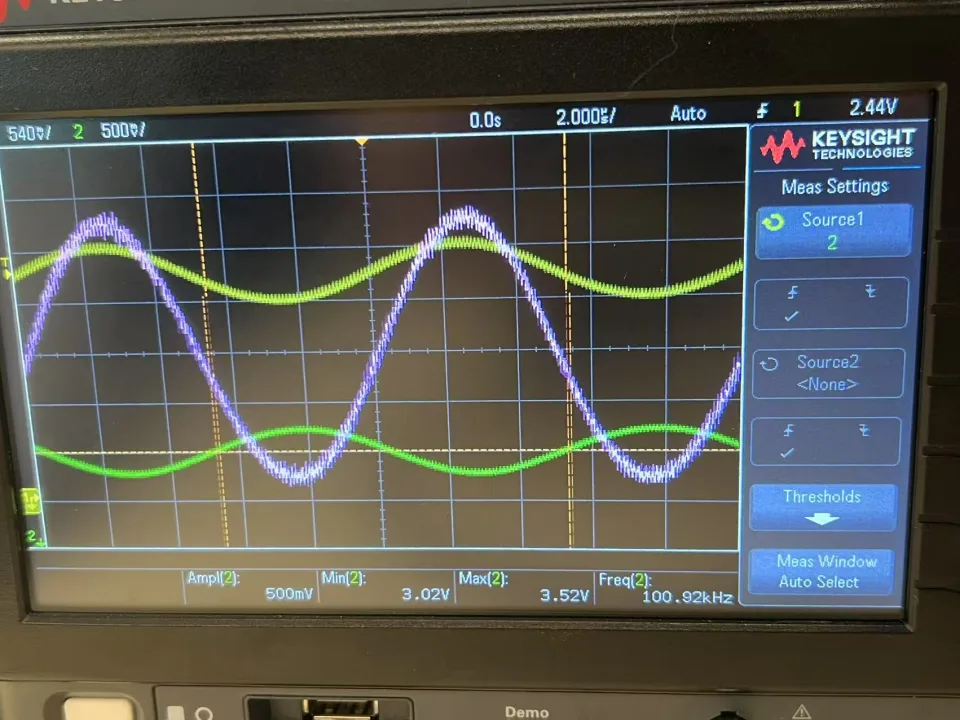
Prototype output near 100 kHz.
From schematic to PCB
The Altium board contains 100+ components across matched I/Q paths, with surface-mount parts, accessible test points, thicker RF traces, and a via fence around the local oscillator. We assembled it using reflow and through-hole soldering.
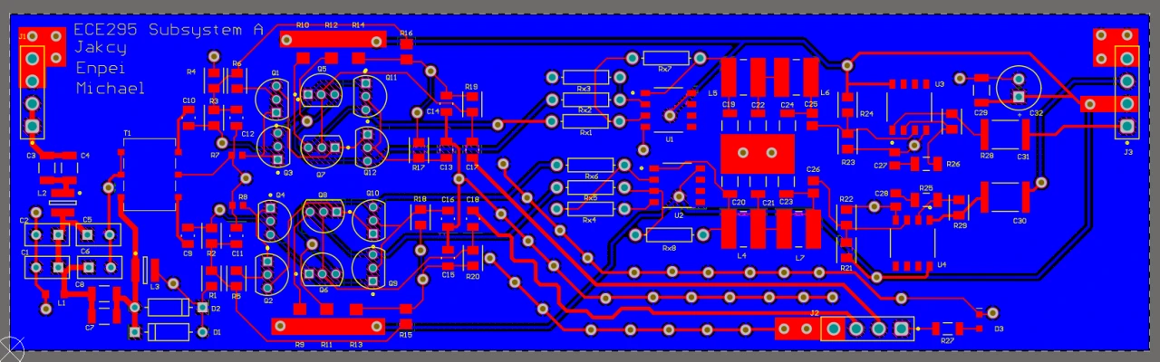
PCB layout in Altium Designer.
Bring-up revealed an incorrect trace and reversed op-amp terminals. We isolated the stage, cut the trace, and added a jumper before resuming tests.
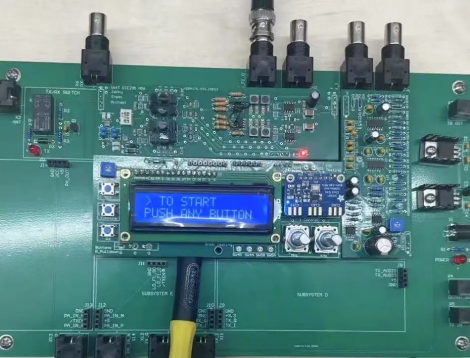
Receiver integrated with the adjacent subsystems.
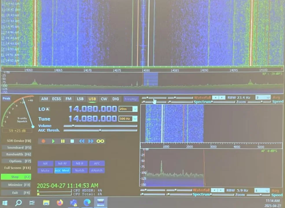
Target signal received by the integrated system.
My contribution
I worked on requirements and designed the bandpass filter, limiter, and Gilbert-cell mixer, including the mixer redesign, simulation, component selection, and prototype testing. A teammate built the PCB; I helped debug it and defined tests for cutoff frequency, limiting, gain, downconversion, and I/Q phase.
Validation & next steps
Bench inputs were 10 MHz at 200 mVpp and a 9.9 MHz, 3.3 Vpp local oscillator with a 1.65 V offset. The output confirmed downconversion near 100 kHz; separate measurements checked the I/Q phase target.
Next: an active low-pass filter for better passband control and gain, independent I/Q adjustments toward the 1 dB imbalance limit, and a pin-and-footprint checklist to prevent bring-up errors.